

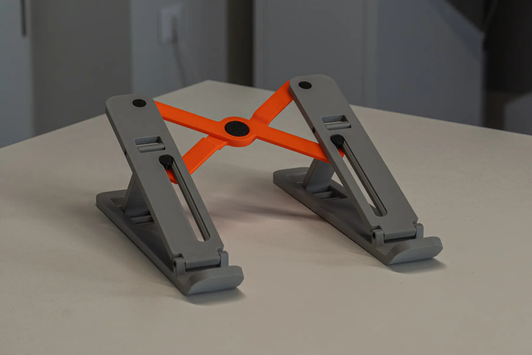
1st Phase: Initial Design
Parametric Strategy & Design Constraints
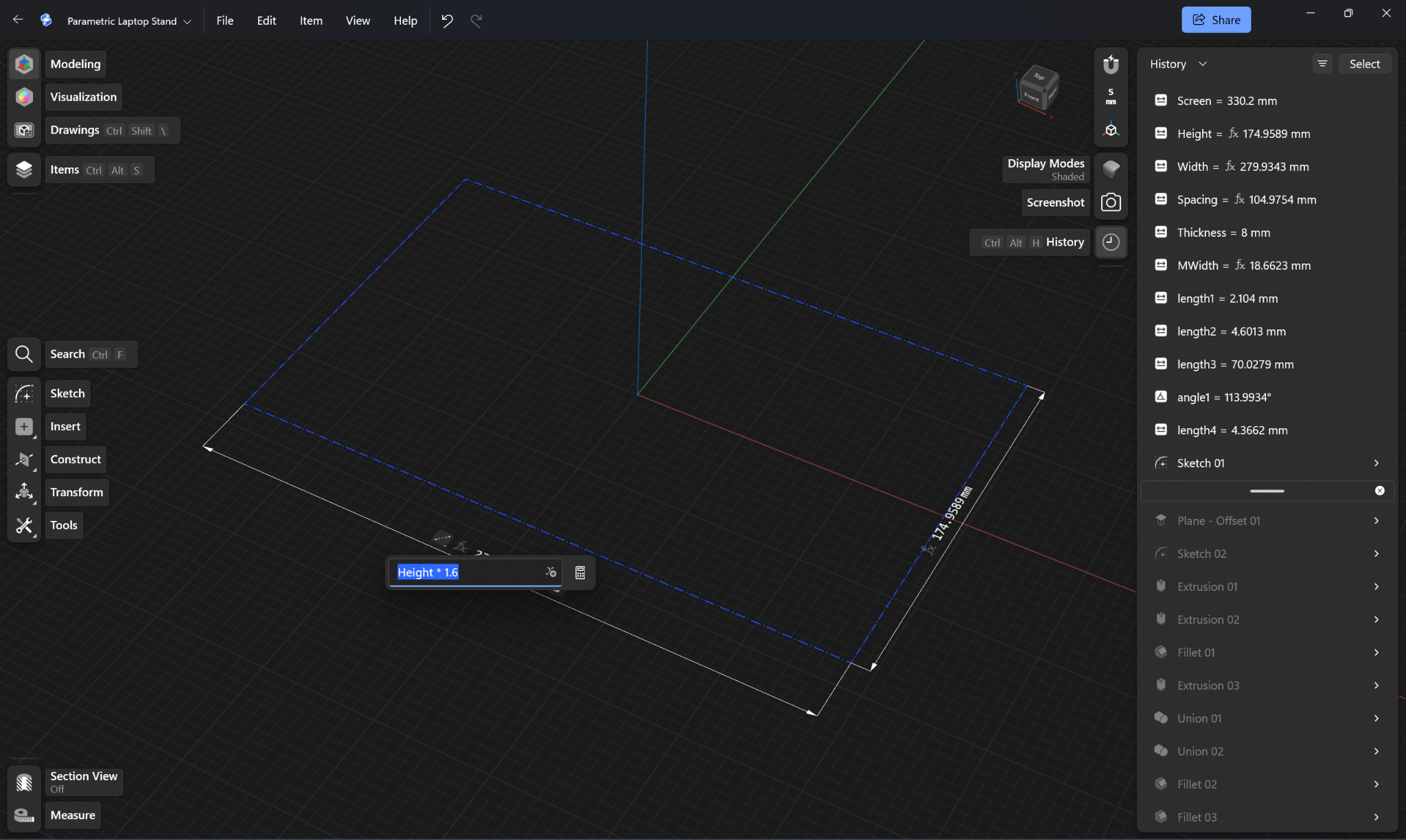
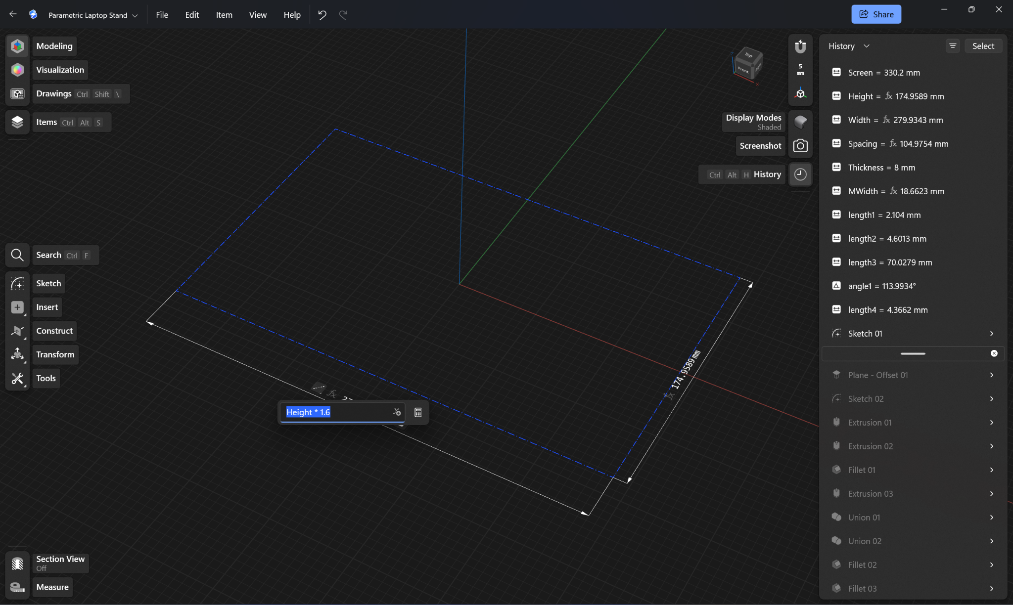
Before modeling any part for 3D printing, it pays to plan ahead. Because this model is parametric, deciding on the main driving numbers and how different parts relate to each other was crucial from the very beginning. Even if the initial plan changes, parametric design lets you make changes easily. Shapr3D is great for this: using the design history, we could step back in time, change basic sizes, and automatically update later steps without breaking the model.
The design process started with researching existing laptop risers and checking them against the realities of 3D printing. We looked at real limits like print bed size, minimum detail size, overhangs, material shrinkage, and print orientation for a high-quality surface.
To make sure the riser works with different laptops, screen size (diagonal) was picked as the main driving parameter. All other dimensions, like overall width, height, and support spacing, were calculated from this one number.
Skeleton Model & Base Geometry
The foundation of the CAD model is a 2D reference sketch called a skeleton. This skeleton acts like a simple line drawing that controls all the 3D parts built on top of it. It includes three main parts: the display skeleton (Fig. 1), based on screen height; the adjusting mechanism skeleton (Fig. 2), which controls how the stand adjusts; and later the folding mechanism, which collapses the riser into a compact form for transport. Keeping this main sketch deliberately unconstrained in one direction let us test different tilt angles by simply dragging the lower point.
A side-profile skeleton was used to calculate the size of the main support arms. The base bars were designed from these dimensions. Their width, length, and thickness are linked to the screen height parameter, so when you change the screen size, the base bars update automatically (Fig. 3).
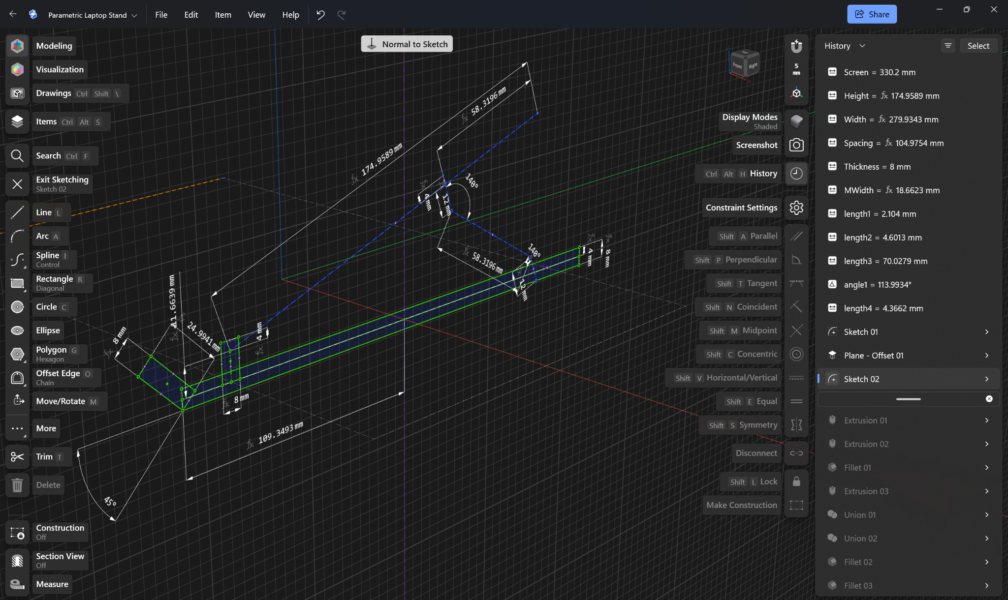
Fig. 3. Base bar
Adjustable Bars & Position Notches
To design the adjustable bars, the side skeleton was used as a guide. By copying line geometry from the skeleton onto a new plane, we created the sketch for the adjustable bar. Linking it this way means any change to the main skeleton automatically updates the adjustable bars later. The 3D shape was made by simply extruding a rectangular profile (Fig. 4).
Fig. 4. Adjustable bars
Next, the height adjustment notches (the slots used to set the laptop angle) were cut into the bars using simple extrusions (Fig. 5). The notch sizes depend on material thickness and screen height: thickness sets the depth along the bar, while screen height sets the width across it. A pattern tool was used to copy the notches down the bar, with spacing based on the screen height (Fig. 6).
Fig. 5.
Fig. 6.
Vertical Support Links & Sliding Slots
The vertical supports connect the base bars and the adjustable bars, locking the riser at different angles. These supports have a custom curved shape made with the Sweep tool. The skeleton was used as the path to follow (Fig. 7), and the cross-section shape was drawn right on top of the adjustable bar. We rounded the corners with fillets to make them stronger and offset the sketch lines slightly to make sure the hole sizes were right (Fig. 8).
Fig. 7.
Fig. 8.
A key feature on the adjustable bar is the sliding slot (Fig. 9), which guides the folding mechanism as it opens and closes. The slot length sets how far the folding arms move, and its position makes sure the folding arms don't hit the vertical supports when collapsed. The slot was placed right in line with the hole for the vertical support (Fig. 10). To stop the sliding pins from sticking out and scratching the laptop, an indentation was added so the pin head sits flat and flush.
Fig. 9.
Fig. 10.
Joint Holes & Modular Pin Strategy
Holes were added at the main pivot points and where the vertical supports attach (Fig. 11). The size of every hole is tied directly to the material thickness setting. If you change the part thickness, the holes scale automatically so the walls stay strong. We used the same hole size expression across all joint points, so the same pins work everywhere.
Fig. 11.
Instead of printing the joints already connected in one piece (print-in-place), which can't be taken apart or repaired, we made separate snap-fit pins (Fig. 12 and Fig. 13). The pin sketches were made directly inside the holes, so if a hole size or part thickness changes, the pin size changes with it. We then copied and moved the pin into all the other holes using the Align tool.
Fig. 12 and Fig. 13
Symmetry & Width Responsiveness
Once one side of the riser was finished, all parts were mirrored across the middle plane (Fig. 14). Because the design started centered on this middle plane, changing the screen size automatically moves the left and right sides further apart or closer together. Larger laptops automatically get a wider, more stable base.
Fig. 14.
Scissor Folding Mechanism Design
The scissor-style folding mechanism keeps the stand stable side to side and lets it fold flat. Construction lines were drawn to mark the paths where the ends of the arms move (Fig. 15). The bottom points slide along the slots, while the top points attach near the top of the adjustable bars. To keep the look balanced, a circular reference line was used to place the top pivot points at equal distances from both edges.
Fig. 15.
Creating the overlapping folding arms without parts colliding required doing the CAD steps in a specific order. Instead of just moving a copy (which breaks parametric links), we used the pattern tool to shift the first arm over by half the thickness parameter (Fig. 16). That copy was mirrored across the center (Fig. 17), and its top surface was extruded up by another half-thickness so the tops lined up flat while creating space underneath.
Fig. 16.
Fig. 17.
Holes were drawn on the skeleton points and extruded straight through to the other side of the arm. Using the Extrude-to-Object setting meant the hole depth automatically matched the arm thickness, even if parameters changed (Fig. 18). Small chamfers were added to the hole edges so the pin heads sit completely flat, leaving a smooth surface for the laptop (Fig. 19).
Fig. 18.
Fig. 19.
Snap-Fit Pin Variations
The initial model ended with designing the different snap-fit pins for the folding joints, slider points, and top pivots. All pins were made using the Revolve tool around the hole's center line. The male pins got a slightly bigger lip at the end and a cut down the middle to let them bend and snap into place. The pins were drawn on one side and mirrored to finish the initial model (Fig. 20).
Fig. 21. Completed model
2nd Phase: Printing and Testing
Once the first CAD model was done, we started 3D printing. We used a Bambu Lab printer and a Prusa Core One. The big structural pieces (base bars and adjustable bars) were printed on the Bambu Lab because of its larger print bed. The smaller pins were printed on the Prusa for better detail. Everything was first printed in PLA (Bambu Orange for the body, Prusa Marble Silver for the pins).
The first full print, with all parameters set to their defaults, went together fine. Testing, however, revealed a few real design problems that needed fixing.
Pin Flexibility & Material Selection
The original 5mm snap-fit pins broke easily during testing. Because the pins were small, the snapping features were less than 1mm thick. This made them weak and prone to snapping along the print layers when pushed into place. We tried different snap designs (cuts in the middle, caps, split cylinders), but none were strong enough in PLA.
To fix this, we redesigned the horizontal pins into simple split sleeves: hollow pins with a slot running down the side. This slot lets the whole pin squeeze down when pushed in and spring back open inside the hole. We also switched the pin material from PLA to black PETG. PETG is tougher and more flexible, stopping the pins from snapping while giving them the springiness needed to click in and out.
For the folding mechanism pins, space was too tight for a normal snap pin. We solved this by making the pin body thicker, widening the slot, and adding a small retention ring on the end. We also made the frame holes slightly bigger for these stronger PETG pins.
Folding Mechanism Clearance & Kinematics
Even though the folding arms moved smoothly, we hadn't accounted for the total thickness of the overlapping arms when closed. When folded flat, the arms bumped into the vertical supports, keeping the stand from closing all the way. We fixed this by creating L-shaped indents on the ends of the folding arms, giving them enough room to clear the supports when folded flat.
To keep the parametric model working properly, we rebuilt the folding mechanism from the skeleton lines up. We recalculated the arm lengths using a circular path guide so that when the stand is fully folded, the sliding pins stop right at the bottom end of the slots. This setup guarantees that no matter what screen size you type in, the folding arms always collapse cleanly without jamming.
Vertical Support Range of Motion
Because of how the vertical supports rotated around their pivot point, they were stuck at less than 90 degrees of rotation instead of moving freely up to 180 degrees. This meant the supports couldn't reach the two lowest angle notches on the base bar.
The fix was easy: we added a bevel (chamfer) to the edge of the hole. This gave the support arm extra clearance to swing further, letting the riser use every single angle notch.
Adjustment Notch Stability & Guidance
The notches held the stand up, but the support arms could slide out sideways while changing positions. We added a shallow guide groove along the notch path to hold the support arm in place and guide it safely into each notch. We also changed the notch shapes: a steeper back wall keeps the stand stable under heavy laptops, while a rounded front edge makes it easier to switch between height settings.
Clearance Calibration & Rapid Tolerance Testing
The biggest issue with the first test print was that all the joints were too loose. Small gaps between pins, slots, and hinges added up, making the whole stand feel wobbly and cheap. To fix the clearances without wasting time and filament on full prints, we cut out small test pieces of just the joints.
We printed and tested small test chips in 0.05mm steps for four main joints: pivot hinges, support arm joints, notch fits, and slider pins. Testing these small parts let us find the exact right clearance for every joint, snug enough to stop wobble but smooth enough to move easily. We then fed these exact measurements back into the full model.
3rd Phase: Updating the Initial Model and 3D Printing
During testing, changes were made quickly using direct modeling tools to save time. But once the final gaps, chamfers, and notch shapes were physically proven to work, all the changes were carefully rebuilt back into the main parametric CAD model. This step was important so the final master file stayed clean, easy to edit, and fully parametric.
The finished model and final print were tested and tuned for a 15-inch laptop. At this size, it easily holds slightly bigger laptops (like 16-inch models) and smaller ones too. While you can change the settings from 11-inch up to 20-inch laptops without breaking the sketch lines, printing and testing those extreme sizes is still a good idea to double-check their strength and fit.
BAMBU, MAIN PARTS, PLA
Quality settings, Bambu
Strength and speed settings, Bambu
PRUSA, PINS, PETG
PRUSA, FOLDING MECHANISM, PLA