


Now that we are adding History-Based Parametric Modeling to Shapr3D, we should talk a bit about what Direct Modeling is, and how Shapr3D will keep supporting it even after the release of our parametric capabilities.
If you’ve already brushed up on the Technological Foundations of CAD, knowing the ins and outs of Direct Modeling (DM) is a relevant next step. First of all, let us define what Direct Modeling is.
Many CAD vendors tried to explain Direct Modeling many different ways, and that created a little confusion around the topic, so let us simplify things (a lot):
Direct Modeling is when the editing of a CAD (boundary representation) model happens without using the parametric history (feature tree) of the model.
Bam. So no, Direct Modeling is not pushing and pulling geometry. Yes, often the interaction model that CAD vendors created to access Direct Modeling operations is push-and-pull. But Direct Modeling operations can be driven and defined by parameters too, just like any other parametric modeling operation. It’s really this simple. So what does this actually mean?
Until 1988, when PTC commercialized the first parametric 3D CAD system in the world (first called PRO/ENGINEER and then rebranded to Creo), every CAD system was a Direct Modeling system, meaning that when you wanted to edit a part, you directly (!) edited the geometry. You used different geometric operations, like Boolean operations to perform modifications. Simple as it is, certain modifications were terribly hard to make with traditional direct editing methods.
For example, let us say that you had a simple part with two holes. You wanted to change the distance between the two holes from 20mm to 25mm. Before PTC invented parametric modeling, you had to invest a lot of cumbersome and manual work to implement such a modification. Either you had to redesign the part from scratch, or you had to perform tricky Boolean operations or surface modeling operations to achieve the desired result. And this is a very simple example - just imagine how tedious it would be to change a more complex model.

Here is where the genius of Samuel P. Geisberg, the founder of PTC, came into the picture: what if instead of just storing the geometry and giving the users a bunch of tools to modify it, we’d record and save the sequence of the modeling operations, so the user could go back to a certain operation anytime, modify some of the parameters, and then “replay” the subsequent operations. So let us say, I could just go back to the operation where I defined the 20mm distance between the two holes, change the 20mm parameter to 25mm and voilà! I have the updated part.
Sounds like magic, isn’t it?
Well, reality is always a little bit less magical. Parametric modeling is brilliant indeed, but like everything in life, it comes at a cost. There are two intrinsic issues with parametric modeling:
- Dependencies: the sequence of operations by definition introduces dependencies between these operations. These dependencies can be hard to understand and sometimes changing a parameter will lead to unintended consequences.
- Rigid changes: the parametric history of a part is the DNA of the part. And just like with organic creatures, while changes that are encoded in the DNA are naturally easy to perform, changes that are not encoded in the DNA can be extremely hard or impossible to perform.
These are the two main issues that lead to most of the pain points of history-based parametric modeling:
- Unexpected changes. For instance, the previous part can be constructed in a way that changing the 20mm parameter to 25mm will result in the part below, and not the expected part above. Is the distance between the two holes 25mm? Yes. Is this what we wanted? Of course not. Why is it broken, then? Well, in this simple case, we could relatively easily find the error, but good luck debugging similar issues with parts that have 1000+ features.

- You need to think ahead, and encode in the parametric history the kind of changes that your part needs to support. Being too flexible will result in very complex or easy-to-break feature trees, while being too restrictive will cause headaches later when unexpected changes occur. Also, you don’t really have a crystal ball to know what kind of changes your customers or stakeholders might want.
- It’s not straightforward how to perform a certain change in a part. Depending on the way the part was created, the same change may need to be performed completely differently. In a parametric, history-based CAD you can create a cylinder by extruding a circle or by revolving a rectangle around one of its sides. In the former case, to change the height of the cylinder, you need to change the height parameter in the extrude operation, and to change the diameter of the cylinder, you need to change the diameter of the circle that you extruded. In the latter case, to change the height of the cylinder, you need to change the length of the side of the rectangle, and to change the diameter of the cylinder, you need to change the length of the other side of the rectangle to diameter/2.
- Making changes can be awfully slow. If your part’s feature tree is made of hundreds or thousands operations, changing a parameter might lead to the re-evaluation of many many operations. This can be very slow in certain cases, particularly with legacy CAD systems.
- Geometry can be transferred between two CAD systems, but parametric history cannot. It has deep technical reasons why it is not possible, but let us just say that basically two CAD systems would need bug-to-bug level compatibility to be able to read and process each other’s parametric history.
Despite all of these issues, parametric modeling became enormously popular over the last few decades, and now it’s the de facto modeling paradigm in the world of engineering software.
However, in 2003 Blake Courter was not happy with parametric modeling - and this is how modern Direct Modeling, and SpaceClaim was born. Blake was frustrated with these limitations of history-based modeling, and tried to figure out an alternative way of editing CAD geometry. Blake wanted to find a way that would enable him to perform changes in part, just purely based on the geometry, without having to tackle all the clumsiness of the parametric history of the part.
The core idea behind modern Direct Modeling is the following:
- Faces can be moved and transformed if we apply smart geometry algorithms to the connecting faces and shrink and extend them.
- Fillets and chamfers can be relatively easily identified and handled as special geometries.
So modern Direct Modeling is really “just” a set of new solid modeling operations that make it possible to perform certain kinds of geometric changes, even without having a parametric history assigned to our geometry. To understand how Direct Modeling actually works, let us take a look at the the most fundamental Direct Modeling operation:
Face Move and Offset Face
As we know it from the Technological Foundations of CAD, every face has an underlying unbounded surface (like a plane or a cylindrical surface), and its outer boundaries and holes are defined by a set of curves laying on the surface.
Here’s basic idea behind the Face Move and Offset Face operations in a few simple steps:
- Detach the face from the connecting faces (leaving some faces open).
- Move the surface of the face in case of a Face Move operation OR offset the surface of the face in the case of an Offset Face operation.
- Extend and/or shrink the open faces to reach the modified face.
- Trim the changed face with the extended/shrunk faces.
- Stitch together everything.
Easier said than done, right? Let us take a very basic example: moving a face of a cube. In this video, we are moving the purple face in the direction of its normal vector. As you can see, the surrounding orange faces are being extended and shrunk as we move the blue face.
We cannot only move, but also rotate the face. In the video below we rotate the face around its center, and just like in the previous example, the surrounding faces are being extended and shrunk by the displaced face to create a solid geometry.

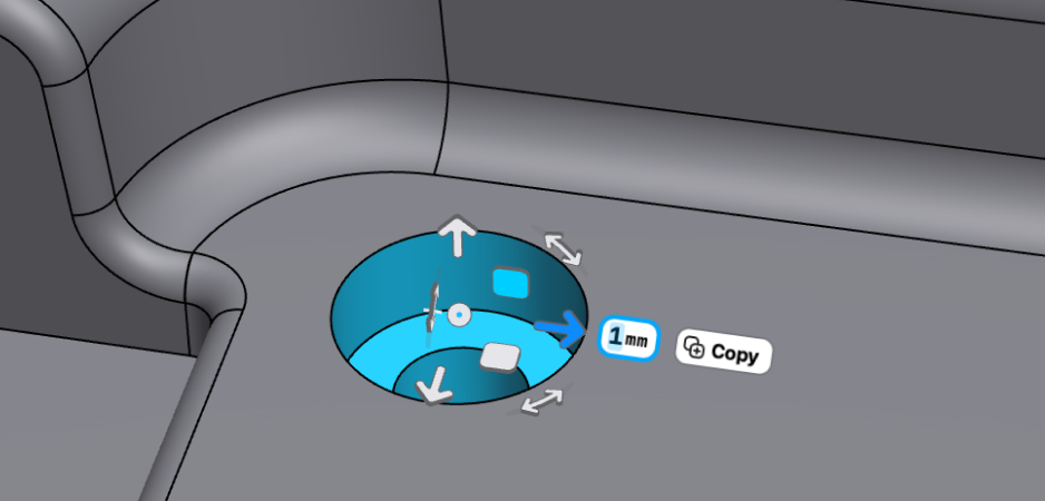
Now that we understand the basics, let us take a look at a real life demonstration. In the example below, we received an iPhone fixture model. It arrived in a neutral CAD format, like X_T or STEP, and imported it to our favorite CAD system, so we don’t have the parametric history of the model. However it turns out that, for some reason, we need to move a hole by 1cm. Without modern Direct Modeling, we’d need to either completely remodel the entire part, or do some cumbersome CAD magic to achieve what we want. However, with modern Direct Modeling, we can easily move the hole 1cm in the desired direction.
While this operation is seemingly more complex than the previous ones, the exact same algorithm is performing very similar operations under the hood. First, it detaches all the faces that we are moving, then it moves the surfaces into place, then it extends or trims the surrounding surfaces guaranteeing that we end up with a watertight, manufacturable solid body.
Offset Face is very similar to Face Move, with the main difference being that the surface of the face is replaced with an offset surface. In the example below, we are applying the Offset Face operation on two holes, changing their diameters.
Now that we understand the most important Face Move and Offset Face operations, we can move on to the third operation.
Face Delete
The philosophy behind Face Delete is very similar to Face Move.
- Removes the selected face(s) by detaching it from the surrounding faces.
- Extends and/or shrinks the surrounding faces to create a closed body.
In the video below, when we delete the yellow face, the blue, the green and the red surfaces will be extended to create a closed body. Then we delete the red face, which will extend the purple, the blue, and the green faces.

And of course, Face Delete works well with more complex geometries, just like the Face Move operation. Going back to our previous example, if we realized that we don’t need the two holes on our fixture, we can easily delete them from the imported model, simply by selecting all the faces of the two holes, and applying the Face Delete operation on them.

Handling Fillets
Fillets are special types of geometries, and by handling them as special cases, we can create more sophisticated algorithms for this particular use case. For example, when we are using the Face Move operation, if we understand that there are faces involved that belong to a Fillet, we can treat them differently. And we can also create a Change Fillet operation, that is optimized for changing the radius of a Fillet. Let us see an example.
Changing a Fillet is similar to the Face Move operation, except that in this case we are not moving the Fillet’s face, but we are replacing it with a rounded face that has a different radius. The Change Fillet operation will
- Remove the selected Fillets by detaching it from the surrounding faces.
- Calculates a new set of rounded faces with the desired radius based on the surrounding faces and replaces the detached Fillet faces with the new faces.
- Extends and/or shrinks the surrounding faces to create a closed body.
In the example below, we are continuously changing the radius of the Fillet, and the blue, red, and yellow faces are being extended and shrunk to create a closed body.

So, when can we apply a Change Fillet Direct Modeling operation? It’s when our CAD system’s geometry kernel thinks that a face belongs to a Fillet. And that’s not an obvious thing to decide. When the Fillets are created in our CAD system, it only remembers whether a certain face was created with a Fillet operation or not, but when it comes to recognizing Fillets on imported models, you aren’t getting obvious answers. When the blend’s radius is very large, and it consumes the surrounding faces, it can be extremely challenging for a geometry kernel to tell if the faces were created by a Fillet operation.
For example, look at the curved faces below. Are those Fillets, or not? Don’t ask your geometry kernel, because you might get a bad answer.

That being said, high-quality geometry kernels, like Parasolid, are fairly good at recognizing blends and applying a Change Fillet operation on them, like in the example below.

Change Fillet operations can be super useful in a history-based environment as well. For example sometimes it happens that you have a properly built feature tree, but due to some dependencies between features, changing a Fillet in your design history would have unintended consequences. In these cases sometimes it’s a good workaround to use the Change Fillet direct modeling operation, as the Change Fillet operation will happen at the end of your feature tree, without messing up your dependencies. Obviously, this is not an ideal solution, but can be a lifesaver when you need it.
Another aspect of Fillets and Direct Modeling is reblending. Reblending is automatically happening when you are using a Move Face or Offset Face operation. When we are applying a Move Face or Offset Face operation, Fillets are handled as special geometries, with different semantics. Modern geometry kernels, like Parasolid, will
- Identify the Fillets.
- Temporarily detach them.
- Apply the Direct Modeling operation.
- Then reapply the Fillets.
This makes working with filleted geometry easy. In the example below we are applying the Offset Face operation on the planar face in the middle of the surrounding Fillets. Parasolid recognizes that the rounded faces are Fillets, and reblends the offseted body accordingly. Note that the radius of the Fillets is not changing due to the Offset Face operation, thus the semantics of our geometry stays the same.

Replace Face
If you understand how Offset Face and Face Move works, Replace Face will be easy. It’s almost the same as those other operations, but instead of changing the face by moving its surface or offsetting it, we can select any face that will replace another face in our geometry.
So the Replace Face operation will
- Detach a selected face from the connecting faces (leaving some faces open).
- Extend and/or shrink the open faces to reach a copy of the target face.
- Trim the copied target face with the extended/shrunk faces.
- Stitch together everything.
The Replace Face operation has many practical applications. The most typical example is when we want to extend a body to a (curved) surface, like in the example below.

It also has some less trivial applications that can be a bit surprising at the first glance. Replace Face can extend or shrink bodies even if the faces don’t fully overlap, only the surfaces need to overlap. In the example below, we are changing the height of the shelled body to match the level of the other planar face. As planes are infinite, Replace Face can detach the top face of the shelled body, and then extend the surrounding faces to the other planar face’s height.
And of course Replace Face works with non-planar faces too, for example we can use it to extend a frying pan’s handle to match the side of the pan.

When Direct Modeling fails
Direct Modeling is a really appealing modeling technique due to its simplicity and intuitive nature. However, it’s not the Holy Grail of CAD. Let us see a few examples where Direct Modeling fails.
The main reason behind most of the failures of Direct Modeling operations is that in many cases, extending or shrinking a face is a challenging task for the geometry kernel - sometimes simply because the face doesn’t exist. One of the typical examples is overlapping Fillets or Fillets with a large radius that “eats away” the surrounding faces. In the demonstration below, we create a Fillet with a larger radius, then we try to delete it.
Unfortunately, we run into an error, because in this case Parasolid won’t be able to figure out how to extend the remaining faces to create a closed body, because the faces on the sides are already lost. Not just that: at the end of the video, we can see that when we select this newly created Fillet, Parasolid no longer recognizes it as a Fillet, but treats it as a general face. Instead of applying the Change Fillet operation, we can apply only the Offset Face operation.

Another thing that can be surprising to Direct Modeling newbies is that it really just works with geometry. So if you lose a part of your geometry, it’s gone. In the example below, we remove half of the part, then we apply the Offset Face operation on the newly created open faces. The result can be somewhat surprising at the first glance: the part starts to “rebuild” initially, but then we end up with a completely different part.
What happens here is completely logical based on what we discussed in this article about Direct Modeling: those faces that are at least partially exist after the boolean cut will be extended due to the Offset Face operation, but the remaining features, like the holes, will not be rebuilt, as those geometries got lost during the Boolean operation, and the Offset Face operation doesn’t know about them anymore. It just works with the existing geometry.
So what is Direct Modeling good for?
There is no free lunch, and no Holy Grail in the world of design and engineering. Just like everything else, Direct Modeling comes with upsides and downsides - but here are a few thoughts on when and how to best incorporate Direct Modeling into your workflow.
- Conceptual design, prototyping, and simple part design
When conceptualizing ideas, building prototypes, or just designing a more simple part, it’s often dramatically faster to not think about a properly built feature tree, and Direct Modeling gives a lot of freedom for incorporating unexpected changes to the design. If your part is very complex, has lots of complex Fillet configurations, shells, hundreds of features - then often you are better off working with a carefully built feature tree. - Combining Direct Modeling with history-based modeling
In certain cases, it can be a lifesaver to add a Direct Modeling operation to the end of your feature tree instead of rebuilding half of your design. Just be thoughtful about it, and be aware of what you are doing. Stacking a ton of Direct Modeling operations in your feature tree may not be a good idea as it simply leads to broken references and hard-to-change models. - Design communication and reviews
When reviewing designs and communicating ideas, Direct Modeling can be a great way to demonstrate your thoughts. “Move this hole 1cm closer to the edge” - just grab the hole and move it there, so everyone will immediately understand what you mean. Direct Modeling can be a quick and efficient way to avoid misunderstandings. - Working with imported geometry
The strongest argument for direct modeling is working with models that don’t have a feature tree, because they come from another CAD system. Using Direct Modeling we don’t need to rebuild the models from scratch, we can make precise modifications using modern Direct Modeling operations.
Direct Modeling can be an incredibly powerful tool in the hands of the skilled CAD designer and it can save you a lot of time and make you more efficient when used correctly. It can eliminate a lot of friction from your workflow - just know how to use it right.